Lever Rule Exterior Girder Example

- the application of the lever rule for exterior beams shall apply - calculate the distribution factor using the tables in article 46222.
Lever rule exterior girder example. Lever rule with calibration versus rigorous example. The LLDF per the equation governs. 35 3963 10 4663 in.
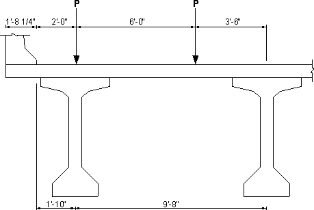
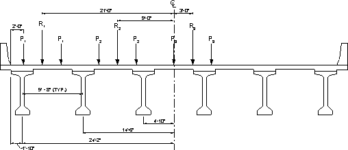
The lever rule is essentially the worst-case scenario for the exterior girder. Place one wheel line from Truck 1 2 ft from girder in bay one and place one wheel line from Truck 2 2 ft away from the same girder. G 75P2 15P2 35P2 75P 0833.
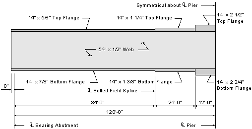
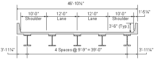
The design process and corresponding calculations for steel I-girders are the focus of this example with particular emphasis placed on illustration of the optional moment redistribution procedures. N 8 NA. Use 5 psf for the unit weight of formwork when it is likely the formwork will remain in place.
The girder and used for lever rule computations. The method of applying dead loads due to utilities is left to. Exterior girder P 2-0 6-0 3-6 P 1-10 9-8 1-8 14 Figure 51-1 Lever Rule Design Step 5111 Calculate the moment distribution factor for an exterior beam with two or more design lanes using Table S46222d-1.
In addition use the rigid cross section equation LRFD C46222d-1 for steel beam bridges. This places the load at d35ft. Moment at 14 One-lane Loaded Exterior I-Girder Calibrated Lever Rule vs.
This study demonstrates that the lever rule method in determining LDFs in two-girder bridge systems using precast trapezoidal U-girders is not overly conservative as comparisons between LDFs from finite-element analysis FEA and the lever rule method of the AASHTO LRFD show that the lever rule method produces values for LDFs that are closely reflective of the actual response for shear and to. The lever rule assumes that the girders act as rigid supports to the bridge deck. Exterior girder distribution factor shall be calculated using the lever rule.


